Time to read: 12 min
Improving part stiffness is critical for load bearing applications, and can be accomplished through both design geometry and material properties. In this article, we’ll employ many of the same formulas we discussed in our previous article about leveraging geometric structures to improve stiffness. However, here we’ll focus on material selection, altering the properties of materials for increased stiffness, and how a project’s budget affects material selection.
First, we’ll detail some specific material properties and how they apply to part stiffness. Then we’ll work through some example problems to understand exactly how we can apply this knowledge.
Material Basics
When an engineer begins to design a new part, the first question should be, “What is the part’s fit and function?”
Why? Well, the application of a component defines the applied loads and the required part strength. Designing for stiffness and rigidity begins with the following.
- Proper material selection
- Understanding the definition of stiffness
- Knowledge of the mechanical properties of materials.
As a design engineer, three factors should be considered when choosing the optimal engineered material for stiffness.
- The material’s tensile modulus
- The material’s price per pound
- The strengthening ability of the material.
Tensile Modulus
The tensile modulus (also known as modulus of elasticity) is a specific property that defines a material’s stiffness. Comparing the tensile modulus of different materials is essential to increasing or decreasing the parts’ stiffness. And when examining the basics of a material’s fit and function, we need to consider the manufacturing processes that alter the mechanical properties of materials.
Heat treating engineering materials is one common process that provides a tremendous advantage when trying to control the stiffness of material. Heat treating is an easy way to increase the stiffness of a material by altering its core hardness.
Stiffness vs Hardness
Hardness: is the ability of a material to resist deformation. This is determined by a standard hardness test, where the surface resistance to indentation is measured.
Stiffness: The measure of a materials ability to return to its original form after being acted on by an external load.
For example, heat treating medium carbon steel alters its properties related to strength, stiffness, hardness, toughness, ductility, and corrosion resistance. For a more in-depth comparison of hardness and strength take a look at our Engineering Fundamentals Refresher. Accounting for material strengthening methods during the design phase provides substantial cost savings because cheaper priced alloys can be used to obtain high tensile strength and stiffness.
Next, let’s compare the tensile modulus of two commonly utilized stainless steel grades (4140 and 316) materials from MatWeb Material Property Data.
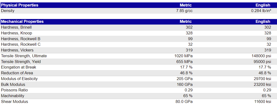
As you can see, 316 Stainless Steel and 4140 Steel are nearly equal in stiffness. And while 316 S.S. has high anti-corrosion properties and excellent stiffness, it may not be the right choice. Depending upon the steel market and location of manufacturing, 316 S.S. is likely to have a higher cost to procure, which drives up project design costs and lead times. Meanwhile, not only does 4140 steel offer superior stiffness, but it’s also more cost effective to heat treat.
Elastic Modulus
The Elastic Modulus of a material, also known as the Young’s Modulus, modulus of elasticity or tensile modulus, is a measure of how easily a material can be stretched or bent. It’s calculated by dividing the longitudinal stress by the strain and is determined by taking the slope of the elastic section of the stress-strain curve for a given material. The modulus of elasticity is the main property that classifies the stiffness of a material. Specifically, think about the comparison we made regarding the modulus of elasticity of steel, and refer to the comparison we made above regarding 316 Stainless Steel and 4140 Steel. Both materials have similar properties, but we can alter them using heat treating processes.
Heat treatment is a process specific to ferrous and non ferrous metals with the goal of altering the atomic structure to increase, or in some instances, decrease the toughness of the material. In other words, if we increase the toughness of a material, we are reducing the modulus of elasticity. For better reference, let us further define both a high and low tensile modulus engineering materials.
High Tensile (Elastic) Modulus Material
Whereas a material having a high modulus of elasticity is defined by its ability to endure high stress with minimum geometric strain, a material with a high tensile modulus will be brittle in structure. To understand the difference, consider a concrete cinder block — the perfect example of an engineered composite material with excellent stiffness. Cinder blocks are designed to withstand high compressive loads, and when under load they will demonstrate minimum amounts of strain. But if we drop a cinder block from a height of 10 feet, it will break apart despite its stiffness because of its brittle structure.
Low Tensile (Elastic) Modulus Material
On the other hand, a low modulus material, like brass, demonstrates the opposite effect. Unlike a concrete block, brass will almost immediately experience strain and begin to deform under compressive loads, but won’t fracture when dropped. If we were to drop a brass block from the 10-foot height, it would absorb the impact when hitting the ground. The brass would become indented by the impact yet remain intact.
This is a great example of stiffness vs. strength — stiffness being a part’s ability to return to its original form after being subjected to a directional force, and strength being the ability to withstand an applied force before permanently deforming or fracturing.
Next we’ll look at some figures to help explain this further, but first, we should define stress and strain:
Stress
Stress is defined as the force per unit area imparted (on a part.) If we suspend a vertical bar that is 1 square inch and equally distribute a load by hanging a 100 lb weight on the bottom, the stress in the bar will be 100 pounds per square inch (psi).
Strain
Strain is defined as the change in length, divided by the original length of a specimen under stress. Going back to our suspended bar example, let’s say that the bar was originally 100 inches, and it stretched a total of 0.25 inches. That means our strain was 0.0025 in/in.
The Stress-Strain Curve
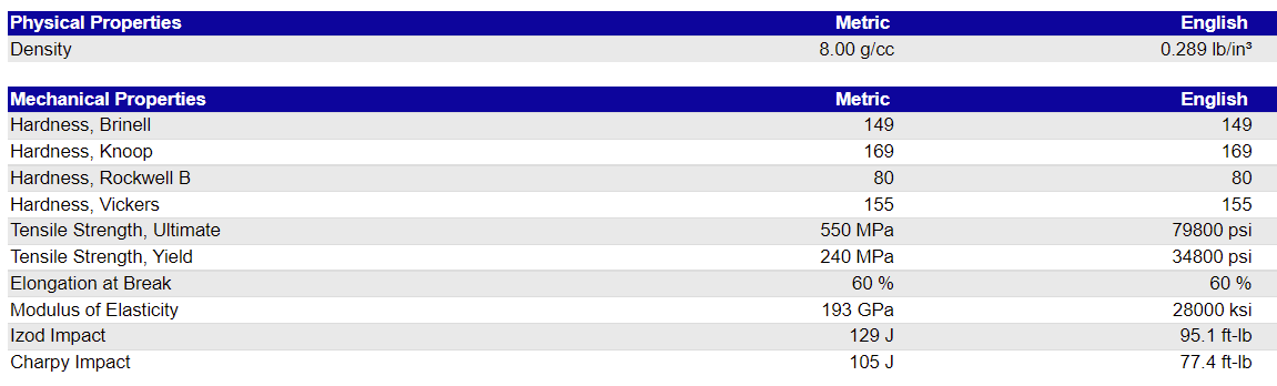
Now that we’ve defined stress and strain, we can talk about the stress-strain curve, which is utilized to determine the elastic modulus. Such a curve is typically developed through testing materials by “stretching” them with specialized machines. The x axis of the curve is the strain value, while the y axis is the stress value. The figure below from the University of Texas at Arlington details the main components of a simple stress-strain curve.
The slope of the elastic region of a stress-strain curve is equal to the stiffness of the material represented by the curve. A material with a steeper slope (concrete) will be stiffer than a material with a shallower slope (brass). This slope of the black line segment is the tensile modulus. Up to the yield point, the material behaves elastically, which means that it will return to its original shape and size after a sustained stress. If we exceed the yield point, the material will be permanently deformed after a sustained stress.
As an example, ABS has a much steeper slope than a rubber band. If we were to examine a stress strain curve for a rubber band the slope would reflect a very small change in incline under a load. Compared to ABS, a rubber band can elongate under a small load without permanent deformation of the material.
Permanent deformation is typically unwanted unless the part is designed to deform such as a rivet or torque value on a fastener. So for the purposes of this article, we’re going to ignor the slope of the non-elastic region of the stress-strain curve because it isn’t used in the formulas or FEA (Finite Element Analysis) studies we’re going to investigate below.
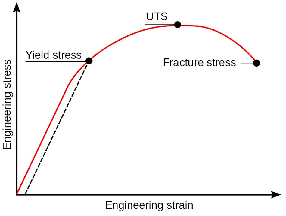
Yield and Ultimate Tensile Strength
Now that we understand the basics of a stress-strain curve, let’s review two of the most important stress values from these curves. The first is the yield strength of a material, which is the highest stress we can place on a material without permanent deformation (indicated by the yield point above). Next is the ultimate tensile strength (UTS) of the material, which is defined as the maximum stress the material can support. The stress-strain curve below has these values labeled. For reference, the failure point is the place where the material physically separates (irrepairably). The proportional limit is the highest stress value for which the stress-strain curve is a straight line; this is the highest stress for elastic deformation. Once the material reaches it’s yield strength (set stress and strain) the material has already started to undergo yielding prior to plastic deformation.
Factor of Safety
When following engineering design best practices, you should always consider implementing a safety factor. The standard formula for a design safety factor concerning mechanical stress is the ratio of allowable material stress (ultimate tensile strength) over the working/designed stress. Fundamentally, a safety factor equal or greater than 1 is the goal. But a good rule of thumb for a safety factor is a target of 1.2. The safety factor formula should be applied anytime there is a change to the materials properties, applied working load, or part geometry. Most FEA software allows for a safety factor data output to go along with the stress, deflection, and strain graphs.
Remember, the design and prototype phases always begin with material selection and the material we choose for our components will define the parts’ stiffness. And correlating our part stiffness to the possibility of failure is a critical part of the design process. As you reduce or increase a part’s stiffness per the application, you must pay attention to concentrated stress points on the part, as those high stress locations are indicators of where the part might fail.
Applied Examples
Before we apply what we’ve learned from stress-strain curves, we need to review some of the formulas discussed in Part 1 of this series.
Formulas of Interest
The first formula defines the deflection of a cantilever beam with a load at one end.
Where:
- δ= Deflection
- P = The Force Applied at the End
- L = The length of the Rod
- E = Elastic Modulus
- I = Area Moment of Inertia (MOI)
Next, let’s revisit our stiffness of material formula:
Finally, we finish with our design for safety factor:
Where:
S.F. = Safety Factor
ult.= Ultimate Tensile Stress
act.= Working or Design Stress
We can see just how the elastic modulus fits in with stiffness through this formula. The relationship is linear, so if we double our elastic modulus, we double the stiffness. Doubling the stiffness means that it will take twice as much force to deflect a part as compared to its original self.
Materials to Consider
The next step in applying this concept is to undertstand the materials we may use and their elastic moduli. The list below details the 3D printed plastics offered by Fictiv and their elastic moduli, along with some metallic materials to demonstrate how high stiffness is directly correlated to material hardness.
Material Elastic Modulus (psi)
AISI 4140 Alloy Steel 275,557,000 to 304,458,000
FDM PLA 293,000 to 514,000
FDM ABS 319,000
VeroWhite/VeroBlack 290,000 to 435,000
SLS Nylon 12 185,000
VisiClear 186,083 to 212,190
UNS C26800 Brass 15,000,000
These values can be found in the Fictiv materials section and may depend on the build orientation of the parts.
In our first applied example, we’ll use Nylon 12 (FDM) and Nylon 12 Glass Filled (SLS) to illustrate a higher contrast between a material of higher stiffness and lower stiffness. The Nylon 12 (FDM) has a modulus of 185,000 psi while the Nylon 12 Glass Filled (SLS) has a modulus of 420,000 psi — that means Nylon 12 Glass Filled is 2.27 times as stiff as regular Nylon 12.
Design Example – Increasing Stiffness
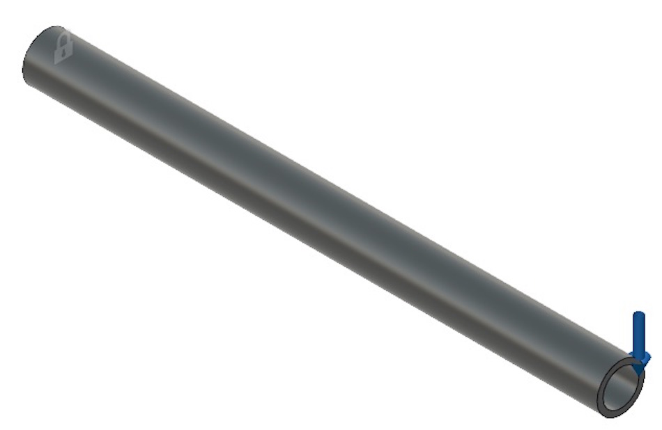
In this first example, we’ll look back at a simple tube that is cantilevered with a force applied at one end. The figure below shows the fixed end with the image of a lock and the loaded end with the arrow pointing downward.
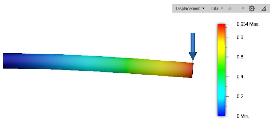
The applied load is 10 lbf, and the first simulation material is Nylon 12, with a modulus of 185,000 psi. The image below, from an FEA simulation depicting the deflection due to the load applied at one end, shows 0.934 inches of deformation.
Now, lets look at the glass filled Nylon 12 GF and see if the stiffness really does increase by a factor of 2.27.
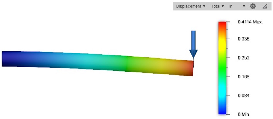
The new deflection is only 0.4114 inches, and if we divide the original 0.934 inches by the new 0.4114 inches, we get exactly 2.27. This tells us that our FEA study agrees perfectly with our increase in material stiffness, because of changing the elastic modulus.
In this example, we’ve used a simple shape, but this concept has real-world application to a variety of geometries. Perhaps you want to increase the stiffness of a plastic hook, so that items don’t fall off under load. Or maybe you need to increase the stiffness of an enclosure or housing so the walls don’t deform or collapse. It’s likely that many plastic parts you use in your everyday life have been carefully designed to achieve the appropriate stiffness.
Design Example – Decreasing Stiffness
In this next example, we’re going to look at a case in which we may want to reduce a part’s stiffness. Consider the snap-fit example from our article on Mechanical Fasteners, shown below.
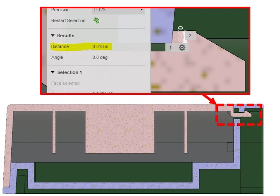
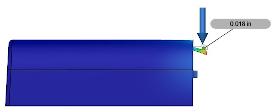
In this image, we can see that the snap-fit must deform 0.018 inches to clear the feature that retains it. However, if the material is stiff, the stresses will be too high in this component when it does undergo 0.018 inches of deflection. Let’s see what the stresses are when the snap deforms this much and the part is made of Nylon 12 GF with a 420,000 psi modulus. The first FEA depiction below demonstrates a 4.136 lbf load generating the 0.018” of deformation.
Once we have achieved the deflection we need, we can look at the stresses that will be present when the part deflects this much. The image below is of the same simulation, but looks at the stresses in the part.
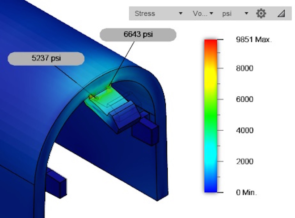
This analysis indicates that we are seeing stresses well more than our 5,250-yield strength, so we will likely damage the part by simply installing and removing this cover. We would almost certainly see stress cracks forming in the corners after a few uses.
But what if we used a material that had a lower elastic modulus, like our original Nylon 12 (185,000 psi)? If you recall from the stress-strain curve, a material with a lower elastic modulus will undergo more strain for a given stress value. In simple terms, that means we can expect the snap to move the same 0.018” with much lower stresses.
When we run the same FEA study with our lower elastic modulus Nylon 12, the load on the snap has been reduced to 1.822 lbf because the lower modulus material requires less force to deflect the same amount.
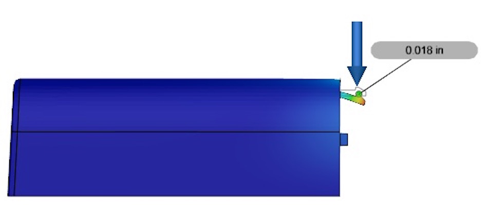
We have achieved the 0.018” of deflection we need, so let’s look at the stresses with which we’re concerned in the image below.
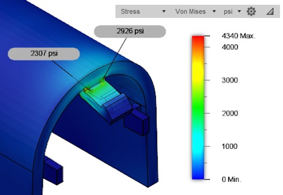
The area that was stressed to 6,643 psi before is now only at 2,926 psi. (And yes, if you do the math, you’ll discover that the stress in the Nylon 12 GF remains exactly 2.27 times as much as the standard Nylon 12.)
This concept can be further expanded to allow for different insertion and removal forces for snap-fit parts, so I encourage you to play around with materials with varying elastic modulus values to get a feel for how they behave.
Next Steps
We hope the principles in this article grow more valuable to you as your material knowledge and material options increase. To check out material options for 3D printing and CNC machining service, visit the Fictiv Hardware Guide.