





Home   ›   Specifications   ›   GD&T Reference

GD&T Quick Reference Guide

Geometric tolerancing symbols, feature control frames, material condition modifiers, and best practices.

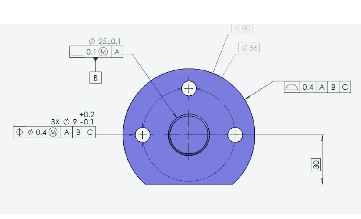
Technical drawing of a blue flange with three outer holes around a central bore; shows dimension lines and datum boxes.
Geometric Tolerance Symbols ▾

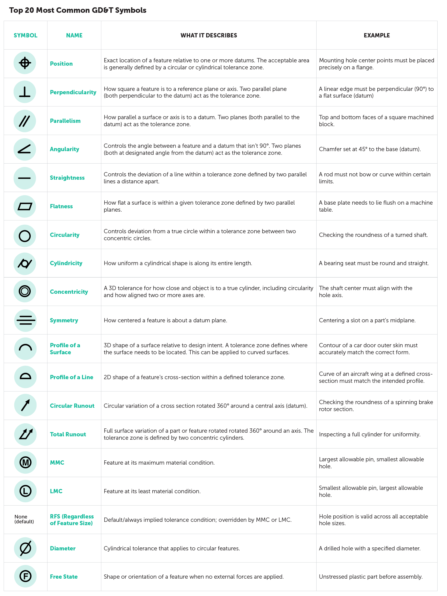
Symbol Name Type Controls
⏤ Flatness Form Between two parallel planes
○ Circularity Form Between concentric circles
// Parallelism Orientation Parallel to datum
⊥ Perpendicularity Orientation Perpendicular to datum
∠ Angularity Orientation At angle to datum
⌖ Position Location True position to datums
◎ Concentricity Location Median points in cyl. zone
↗ Circular Runout Runout Variation per rotation
↗↗ Total Runout Runout Full surface variation
Feature Control Frame ▾
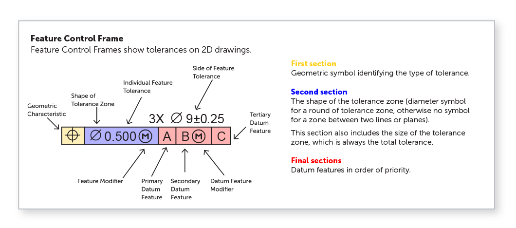
  • Reading order: Symbol → Tolerance Zone → Material Condition → Datums
  • Example: |⌖| Ø0.050 |M| A | B | C |
  • Ø = cylindrical zone. No Ø = total wide zone.
How to read a feature control frame.
Material Condition Modifiers ▾
Name Meaning
MMC Max material. Bonus tolerance as feature departs.
LMC Least material. Bonus tolerance applies.
RFS All sizes. Default if none specified.
Datums & Reference Frames ▾
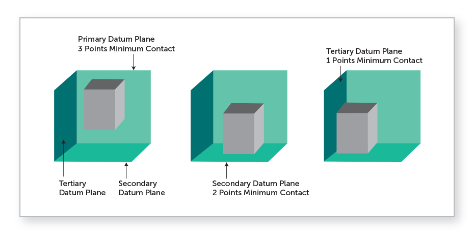
Datum planes (primary, secondary, and tertiary).
  • Primary (A): 3 DOF (plane)
  • Secondary (B): 2 DOF (line)
  • Tertiary (C): 1 DOF (point)
  • A-B-C = fully constrained (6 DOF)
  • Datum targets for cast/forged parts
Best Practices ▾
  • Apply GD&T only where function requires
  • Use MMC on fastener holes for bonus tolerance
  • Establish datums based on assembly function
  • Keep datum references consistent across drawings
  • Consider: can it be measured with available equipment?
  • Reference: ASME Y14.5-2018

Questions about GD&T?

Guide to GD&T →

Expert DFM feedback on every order.